In this article:
Introduction
Enable the Vision Switcher
Vision Switcher Status Explained
Protocols, Channel Offset, Break Duration and Testing
Common Vision Switchers and Protocols
Introduction
CuePilot connects to a Vision Switcher to remote control it. When CuePilot has control of the Vision Switcher, it is able to execute Vision Cues, switching between channels and routing the correct camera to line, based on the Vision Cues in a Vision Track in an Act's Timeline.
With a Vision FX Track, CuePilot is also able to execute macros, effects and keying on the Vision Switcher.
Connecting the CuePilot application to a Vision Switcher requires CuePilot Studio Server hardware, such as a Nexus Studio Server, S6 Studio Server, or BOB unit.
CuePilot's Studio Server hardware either connects to a Vision Switcher over its RS422 port through a CuePilot C1 Certified serial cable to the Vision Switcher's remote port, or over IP through a network connection.
Enable the Vision Switcher
Connect the supplied C1 Certified Serial Cable to the Vision Switcher's remote port as well as the CuePilot Studio Server's remote port.
C1 cables have a special pin allocation to force the communication to be over RS422. Learn more about the C1 Certified Serial Cable....
Ensure that the Vision Switcher has remote control enabled in its system. If the Vision Switcher is not configured to allow remote control then CuePilot will not be able to control it. Consult the user manual or manufacturer if necessary.
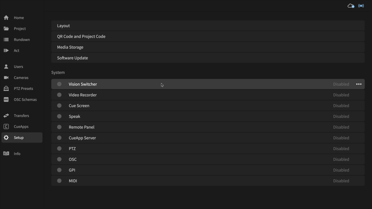
- In CuePilot, enable the Vision Switcher by going to Setup, selecting Vision Switcher and changing the Status to Enabled.
- Select the corresponding protocol that the Vision Switcher accepts. See below for Common Vision Switchers and Protocols.
- Select Reconnect. CuePilot will establish a connection with the Vision Switcher.
If you quit CuePilot and the Vision Switcher was enabled, when you reopen the application again it will automatically reconnect to the Vision Switcher on launch.
Vision Switcher Status Explained
The buttons at the top of the Vision Switcher setup dialog show the status of the communication.
DEV: Device Found Status
Gray: Not Set. This indicates that the CuePilot application has not yet attempted to connect to CuePilot Studio Server hardware. Select Reconnect to connect.
Green: Device found. This indicates that the CuePilot application has successfully connected to the CuePilot Studio Server hardware.
Red: Device not found This indicates that the CuePilot application can not connect to the CuePilot Studio Server hardware. Check whether the cable is securely attached to the correct device and then select Reconnect to connect.
COM: Communication Port Open Status
Gray: Not set. This indicates that the communication port is inactive.
Green: Com port open. This indicates that the communication port is open, meaning the CuePilot application has open communication with the CuePilot Studio Server hardware.
Red: Com port NOT open. This indicates that the communication port is not open.
TX: Transmit Status
Gray: Not transmitting. This indicates that there is currently no data being transmitted from the CuePilot Studio Server hardware. This is normal and the TX/RX status will only flicker green momentarily as data is sent and received.
Green: Transmitting data. This indicates that data is being transmitted from the CuePilot Studio Server hardware.
Red: Transmit error. This indicates that there is a data transmitting error.
RX: Receive Status
Gray: Not receiving. This indicates that there is currently no data being received by the CuePilot Studio Server hardware from the Vision Switcher.
Green: Receiving data. This indicates that data is being received by the CuePilot Studio Server hardware from the Vision Switcher.
ACK: Acknowledge Status
Gray: Not set. This indicates that the Vision Switcher status is inactive.
Green: Switcher connected. This indicates that the Vision Switcher is connected and that the CuePilot application has received an acknowledgement back, a hex value of '84'.
Red: Switcher not connected. This indicates that the Vision Switcher is not connected and that the CuePilot application has received a not acknowledged back, a hex value of '85'.
Protocols, Channel Offset, Break Duration and Testing
Serial Protocols supported in CuePilot:
- GVG
- GVG Kayak
- GVG Kayenne
- Sony
- Sony Serial Tallyport
- ROSS
- Panasonic
IP Protocols supported in CuePilot:
- Blackmagic Design ATEM
99% of all professional production switchers support at least one of these protocols. The correct protocol to use will depend on your Vision Switcher.
Channel Offset. When setting up a Vision Switcher connection, you may need to apply a channel offset. In CuePilot, by default, camera one is channel 1 on the Vision Switcher. Camera two is channel 2, and so on.
You can use Channel Offset to apply an offset to the channels. For example, if cameras one to ten are meant to be channels 101 to 110 on the Vision Switcher, you can apply a channel offset of +100. Then when CuePilot selects camera one, the Vision Switcher will select channel 101.
Break Duration
Vision Switchers may only accept remote control by an external device if the break duration meets its criteria. Some Vision Switchers can be more strict or more forgiving. By default CuePilot uses a break duration of 5 milliseconds. If you need to, you can adjust the break duration to meet the Vision Switchers requirements.
Testing
At the bottom of the Vision Switcher setup dialog, you can use the Test buttons to quickly simulate adding cues to the timeline and playing them back. This lets you quickly troubleshoot outputs and offsets without having to leave the setup dialog. Use the buttons 0 to 4, for example, 1 for camera one, and check with the vision switcher if it applied the cut correctly. Click back and forth on the buttons to test and adjust settings until the Vision Switcher is behaving correctly.
Common Vision Switchers and Protocols
- Sony Vision Switchers: Use Sony protocol.
- Sony Vision Switchers with Tallyport: Use Sony Serial Tallyport. Please note a crossover serial adapter may be required.
- Blackmagic Design ATEM Vision Switchers: Use GVG protocol when connected over serial.
- Blackmagic Design ATEM Vision Switchers: Use ATEM protocol when connected over IP.
- Grass Valley Group Vision Switchers: Use GVG, GVG Kayenne or GVG Kayak protocol.
- Panasonic Vision Switchers: Use Panasonic protocol.
- Ross Vision Switchers: Use Ross protocol.
Learn more:
C1 Certified Serial Cable...
MIDI on Vision Cues...
Video Tutorial: Vision Track Editing...
Blackmagic Design ATEM Switcher connection over IP...